|
Geometry Characteristics
|
|
Core Diameter
|
--
|
50±2.5
|
[μm]
|
|
Core Non-Circularity
|
--
|
≤5.0
|
[%]
|
|
Cladding Diameter
|
--
|
125.0±1.0
|
[μm]
|
|
Cladding Non-Circularity
|
--
|
≤0.6
|
[%]
|
|
Coating Diameter
|
--
|
245±7
|
[μm]
|
|
Coating/Cladding Concentricity Error
|
--
|
≤10.0
|
[μm]
|
|
Coating Non-Circularity
|
--
|
≤6.0
|
[%]
|
|
Core/Cladding Concentricity Error
|
--
|
≤1.0
|
[μm]
|
|
Delivery Length
|
--
|
up to 8.8
|
[km/reel]
|
|
Optical Characteristics
|
|
Attenuation
|
850nm
|
≤2.4
|
[dB/km]
|
|
1300nm
|
≤0.6
|
[dB/km]
|
|
--
|
--
|
MaxBand® OM2+/OM3/OM4 Bend Insensitive
|
|
Overfilled Modal Bandwidth
|
850nm
|
≥700/≥1500/≥3500
|
[MHz·km]
|
|
1300nm
|
≥500/≥500/≥500
|
[MHz·km]
|
|
Effective Modal Bandwidth
|
850nm
|
≥950/≥2000/≥4700
|
[MHz·km]
|
|
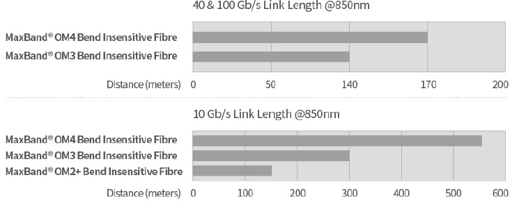
Application support distance on
|
--
|
--
|
--
|
|
40GBASE-SR4 / 100GBASE-SR101
|
850nm
|
-/140/170
|
[m]
|
|
10GBASE-SR
|
850nm
|
150/300/550
|
[m]
|
|
1000BASE-SR
|
850nm
|
750/1000/1100
|
[m]
|
|
DMD Specification
|
Compliant with and more stringent than the requirements of IEC60793-2-10
|
--
|
|
Numerical Aperture
|
--
|
0.200±0.015
|
--
|
|
Group Refractive Index
|
850nm
|
1.482
|
--
|
|
1300nm
|
1.477
|
--
|
|
Zero Dispersion Wavelength(λ0)
|
--
|
1295-1340
|
[nm]
|
|
Zero Dispersion Slope(S0)
|
1295nm≤λ0≤1310nm
|
≤0.105
|
[ps/(nm2·km)]
|
|
1310nm≤λ0≤1340nm
|
≤0.000375(1590-λ0)
|
[ps/(nm2·km)]
|
|
Macrobending Loss2
|
--
|
--
|
--
|
|
2 Turns @ 15 mm Radius
|
850nm
|
≤0.1
|
[dB]
|
|
1300nm
|
≤0.3
|
[dB]
|
|
2 Turns @ 7.5 mm Radius
|
850nm
|
≤0.2
|
[dB]
|
|
1300nm
|
≤0.5
|
[dB]
|
|
Backscatter Characteristics
|
1300nm |
|
|
Step(Mean of Bidirectional Measurement)
|
--
|
≤0.10
|
[dB]
|
|
Irregularities Over Fibre Length and Point Discontinuity
|
--
|
≤0.10
|
[dB]
|
|
Attenuation Uniformity
|
--
|
≤0.08
|
[dB/km]
|
|
Environmental Characteristics
|
850nm & 1300nm |
|
|
|
Temperature Cycling
|
-60℃ to 85℃
|
≤0.10
|
[dB/km]
|
|
Temperature-Humidity Cycling
|
-10℃ to 85℃,4% to 98% RH
|
≤0.10
|
[dB/km]
|
|
Water Immersion
|
23℃, 30 days
|
≤0.10
|
[dB/km]
|
|
Dry Heat
|
85℃,30 days
|
≤0.10
|
[dB/km]
|
|
Damp Heat
|
85℃, 85% RH,30 days
|
≤0.10
|
[dB/km]
|
|
Mechanical Specification
|
|
Proof Test
|
--
|
≥9.0
|
[N]
|
|
--
|
≥1.0
|
[%]
|
|
--
|
≥100
|
[kpsi]
|
|
Coating Strip Force
|
typical average force
|
1.5
|
[N]
|
|
peak force
|
≥1.3, ≤8.9
|
[N]
|
|
Dynamic Stress Corrosion Susceptibility Parameter(nd, typical)
|
--
|
20
|
--
|