FarBand® Ultra fibre complies with or exceeds the ITU-T G.654.B/E recommendation and IEC 60793-2-50 B1.2 specification.
FarBand® Ultra Low Loss and Large Effective Area Fibre
For the next generation optical transmission network, lower attenuation or larger effective area of the fibre can help the system meet 3U (Ultra high speed, Ultra large capacity, Ultra long-haul) features. Now YOFC can deliver you larger effective area and lower attenuation within one fibre: FarBand® Ultra.
Details
Specification
Documents
Product standards
Product advantage
• Larger effective area reduces nonlinear effect and enables higher signal power launched into the transmission system.
• Enable higher transmission speeds with more wavelengths over ultra long-haul distances.
• Lower attenuation level which meets the demand of extended long distance transmission
• Reduce number of repeaters and minimize CAPEX and OPEX.
• Lower bending induced loss to meet complicated deployment conditions and cable structures.
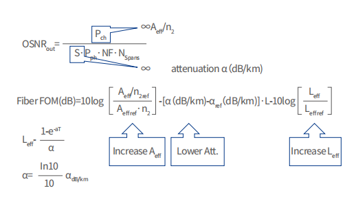
How to calculate the contribution of larger effective area and lower attenuation?
Based on the formula of OSNR, lower attenuation and larger effective area will increase OSNR of optical transmission system. And FOM (Figure of Merit) is established to calculate the contribution of effective area and attenuation. As shown in the table, YOFC ultra low loss and large effective area fibre can provide greater performance improvement than ultra low loss fibre below, or low loss and large effective fibre.
|
Fibre Type |
Att. |
Aeff. |
FOM |
|---|---|---|---|
|
SSMF(Ref.) |
0.2 |
80 |
/ |
|
LL |
0.18 |
80 |
1.6 |
|
ULL |
0.17 |
80 |
2.3 |
|
ULL |
0.15 |
80 |
3.8 |
|
LL-LAF |
0.18 |
130 |
4.9 |
|
ULL-LAF |
0.16 |
110 |
5.8 |
|
ULL-LAF |
0.16 |
130 |
6.4 |
Specifications
|
Characteristics |
Conditions | Specified values | Units | |||
|---|---|---|---|---|---|---|
|
Optical Specifications |
||||||
|
Nominal Effective Area |
1550nm |
110 |
125 |
[μm2] |
||
|
Mode Field Diameter |
1550nm |
11.4-12.2 | 12.0-13.0 |
[μm] |
||
|
Attenuation |
1550nm |
≤0.17 |
[dB/km] |
|||
|
1625nm |
≤0.20 |
[dB/km] |
||||
|
Attenuation vs. Wavelength Max. α difference |
1525-1575nm, in reference to 1550nm |
≤0.02 |
[dB/km] |
|||
| 1550-1625nm, in reference to 1550nm |
≤0.03 |
[dB/km] |
||||
|
Dispersion Coefficient |
1550nm |
≤23 |
[ps/nm·km] |
|||
|
1625nm |
≤27 |
[ps/nm·km] |
||||
|
Dispersion Slope |
1550nm |
0.050-0.070 |
[ps/nm2·km] |
|||
|
PMD |
Maximum Individual Fibre |
-- |
≤0.1 |
[ps/√km] |
||
| Link Design Value(M=20,Q=0.01%) |
-- |
≤0.06 |
[ps/√km] |
|||
| Typical Value |
-- |
0.04 |
[ps/√km] |
|||
|
Cable Cutoff Wavelength (λCC) |
-- |
≤ 1520 |
[nm] |
|||
|
Effective Group Index of Refraction |
1550nm |
1.463 |
1.465 |
-- |
||
|
Point Discontinuities |
1550nm |
≤0.05 |
[dB] |
|||
|
Geometrical Specifications |
||||||
|
Cladding Diameter |
-- |
125.0±1.0 |
[μm] |
|||
|
Cladding Non-Circularity |
-- |
≤1.0 |
[%] |
|||
|
Coating Diameter |
-- |
235-255 |
[μm] |
|||
|
Coating-Cladding Concentricity |
-- |
≤12 |
[μm] |
|||
|
Coating Non-Circularity |
-- |
≤6 |
[%] |
|||
|
Core-Cladding Concentricity |
-- |
≤0.6 |
[μm] |
|||
|
Fibre Curl(Radius) |
-- |
≥4 |
[m] |
|||
|
Delivery Length1 |
-- |
Up to 25.2 |
[km/reel] |
|||
|
Environmental Specifications @1550nm & 1625nm |
||||||
|
Temperature Dependence |
-60℃ to +85℃ |
≤0.05 |
[dB/km] |
|||
|
Temperature-Humidity Cycling |
-10°C to +85°C, 98% RH |
≤0.05 |
[dB/km] |
|||
|
Water Immersion |
23°C,for 30 days |
≤0.05 |
[dB/km] |
|||
|
Damp Heat |
85°C , 85% RH,for 30 days |
≤0.05 |
[dB/km] |
|||
|
Heat Aging |
85℃,30 days |
≤0.05 |
[dB/km] |
|||
|
Mechanical Specifications |
||||||
|
Proof Test2 |
-- |
≥9.0 |
[N] |
|||
|
-- |
≥1.0 |
[%] |
||||
|
-- |
≥100 |
[kpsi] |
||||
| Macro-bend Induced Loss | 100 Turns Around a Mandrel of 30 mm Radius |
1550nm |
≤0.10 |
[dB] |
||
|
1625nm |
≤0.10 |
[dB] |
||||
|
Coating Strip Force |
typical average force |
1.5 |
[N] |
|||
|
peak force |
1.3-8.9 |
[N] |
||||
|
Dynamic Fatigue Parameter(nd) |
-- |
≥20 |
-- |
|||
Remark: 1. Other delivery lengths are available. 2. Higher proof test level is available.
Brochure
Papers
- 2019 ECOC 4463974 China Mobile (ULL-G654-A110)
- 2019 SR China Mobile s41598-018-36064-1 (ULL-G654-A110)
- 2016 OFC Tu3G.2 ZHY-A Bend-insensitive Ultra Low Loss and Large Aeff fibre for Long Haul transmission (ULL-G.654-A110)
- 2017 OFC W2A.23 Novel Ultra Low Loss & Large Effective Area G.654.E Fibre in Terrestrial Application (ULL-G654-A110)
- 2018 CLEO-PR Tu2I.5 Longest-ever unrepeatered transmission over 713.2km of 2.5 Gbs with a span loss in excess of 111dB (ULL-G654-A110)
- 2018 OE Integrating quantum key distribution with classical communications in backbone fiber network oe-26-5-6010 (ULL-G654-A110)
- 2019 JLT Unrepeatered Transmission over 670.64km of 50G BPSK, 653.35km of 100G SP-QPSK, 601.93km of 200G 8QAM and 502.13km of 400G 64QAM(ULL-G654-A130)
- 2019 OFC M2E.2 50G BPSK, 100G SP-QPSK, 200G 8QAM, 400G 64QAM ultra long single span unrepeatered transmission over 670.64km, 653.35km, 601.93km and 502.13km respectively (ULL-G654-A130)
- 2020 OFC Th1D.2 Single-Carrier 500Gbs Unrepeatered Transmission over a Single 431km Span with Single Fiber Configuration (ULL-G654-A130+150)
Related products