- Thunderstorms, electrical failures, loose electrical connections and operator errors can lead to serious accidents.
- Transformer casing fires and capacitor explosion are possible in substations.
- Cable faults can also cause fires, due, for example, to quality problems of cable joints or insulator aging after long-time operation. Single-phase ground short circuit faults can occur in cables on the low-voltage side of transformer. Short distances between cables, or insufficient safety gaps can lead to arcing when voltages are applied, causing cable fires. Debris accumulation can limit cables' heat dissipation, leading to high local temperatures and possibly fire.
Ensuring the safety of power supply apparatus to prevent such accidents creates an urgent need for a system capable of online, real time monitoring of cables and equipment that can accurately measure temperatures, precisely locate faults, and connect with back-end fire control systems.
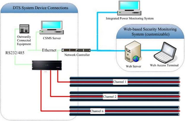
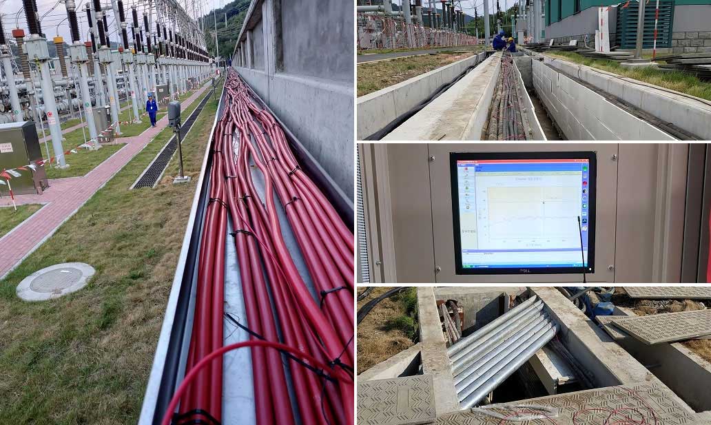
In this project's cable trenches, the cable bundles for each direction include a temperature sensing optical cable for online temperature monitoring, secured with insulating tape every 1.5 m. There are 8 cable trenches and 127 protection zones, with total length of about 5 km.
Each temperature sensing optical cable is connected via a junction box to the DTS host through a fibre optic pigtail.
Temperature sensing optical cables must be installed close to the detection area so that they can rapidly detect increases in temperature or fire. A temperature sensing optical cable was laid in a wavy shape over each cable trench in all direction.


Substation cable and equipment temperature monitoring software were customized for intelligent visual monitoring and management of substation temperature to fulfill client requirements:
- When alarm is triggered by a detector set to a fixed temperature, an alarm window popup appears;
- The names of the 8 channels and 127 protection zones can be customized to suit client requirements;
- Temperature information for all 8 channels in the protection zones is routinely displayed;
- A status overview interface can be added, based on client requirements. This would normally display the times temperature alarms have been triggered on each channel, blinker unit for fibre break alarm and blinker unit for equipment fault alarm;
- Alarm threshold information for all 8 channels is routinely displayed;
- Firewall locations on the electronic map can also be modified to suit client requirements;
- Fibre break alarm status is routinely displayed;
- With the software deployed on the substation server, the monitoring interface can be routinely displayed in the substation monitoring room;
After completion of the project, cable temperatures can be measured online in real time. The system is connected on an area by area (127 areas) basis with the fire control system, and actual fault locations displayed on the map, facilitating comprehensive management of this data by the substation managers. Strong data analysis capability: the system can conduct big data analysis on cable across the time and line dimensions, providing a basis for cable life cycle and load management:
- Cable and equipment temperatures in the whole substation can be monitored online 24 hours a day from the duty room, to ±1 °C accuracy.
- Functionality including fixed temperature, temperature increase, temperature difference and fault alarms, and alarm area localization have been incorporated, with positioning accuracy of ±1 m;
- System data reports are stored and associated with the actual map. Truly intelligent and digitalized, this system greatly improves substations' fire early warning capabilities.
