The terrestrial network in China is mainly subject to the ordinary G.652.D optical fibre currently, while most of the optical cable laid in 1990s and have reached 20 --25 years’ service life, therefore, the backbone network should be upgraded gradually in the next few years. Therefore, how to choose the right optical fibre for the long-distance terrestrialoptical cable is a key problem urgent to be solved for the network operators and optical communication companies. In order to obtain the best system performance, if we can combine the ultra-low attenuation and large effective area characteristics into an optical fibre, such optical fibre will be the best optical fibre in the next-generation communication optical fibre.
1. G.654.E Recommended indicators
The following table shows the currently discussed G.654.E optical fibre indicators and YOFC ultra-low loss large effective area optical fibre datasheet. the ultra-low attenuation large effective area optical fibre (FarBand ® Ultra) of YOFC can meet and even be better than the most existing stringent G.654.E standard recommendation proposals.
|
Parameter name |
G.654.E discussion paper |
YOFC Scope of product manual |
||||
|
Proposal 1 |
Recommendation 2 |
|||||
|
E1 |
E2 |
|||||
|
Optical parameters |
|
|||||
|
*Mode field diameter @ 1550nm (um) |
Nominal |
11.5-13.0 |
11.0-12.0 |
12.0-13.0 |
11.4-12.2 Typical: 11.8 |
|
|
Deviations |
±0.7 |
±0.7 |
±0.7 |
|
||
|
Effective area typical value @ 1550nm (um2) |
\ |
\ |
\ |
110 |
||
|
*Optical cable cut-off wavelength (nm) |
≤1510 |
≤1530 |
≤1530 |
≤1530 Typical value 1440nm |
||
|
*Attenuation coefficient @ 1550nm (dB / km) |
≤0.20 |
≤0.20-0.25 |
≤0.174 (Typical 0.160) |
|||
|
*Macro-bending (R30mm × 100 turns) |
1550nm (dB) |
TBD |
TBD |
TBD |
≤0.1 |
|
|
1625nm (dB) |
≤0.2 |
≤0.5 |
≤0.5 |
≤0.2 |
||
|
*Dispersion coefficient @ 1550nm (ps / nm / km) |
≤22 |
≤22 |
≤22 |
≤22 |
||
|
dispersion slop @ 1550nm (ps / nm2 / km) |
≤0.070 |
≤0.070 |
≤0.070 |
≤0.070 |
||
|
PMD (ps/km1/2) |
≤0.2 |
≤0.2 |
≤0.2 |
≤0.2 |
||
|
Geometric Parameter |
|
|
|
|
||
|
Cladding outer diameter (um) |
125±1 |
125±1 |
125±1 |
125±1 |
||
|
Core cladding concentricity (um) |
≤0.8 |
≤0.8 |
≤0.8 |
≤0.8 |
||
|
Cladding circularity (%) |
≤1.0 |
≤1.0 |
≤1.0 |
≤1.0 |
||
*Still under discussion, ITU-T Q5 group has no specific recommendations.
2. Design and manufacturing of optical fibre

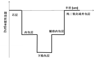
Schematic diagram for optical fibre refractive index profile structure
Compared YOFC the ultra-low loss large effective area optical fibre with the traditional fluorine-doped external cladding structure ULL fibre, YOFC adopts pure silicon dioxide (SiO2) as the optical fibre cladding, due to the reduction in the use amount of fluorine-doped materials, in terms of material preparation cost, preparation technology difficulty, environmental protection and other points of view, our ultra-low attenuation large effective area optical fibre products are more competitive in the cost.
3. Optical fibre and optical cable performance
3.1 Optical fibre attenuation
In terms of theory and practical points of view, the lower attenuation can reduce the number of repeaters and reduce the maintenance costs of long-haul communication network; therefore the continuous reduction in the optical fibre attenuation coefficient is the long-term goal of optical fibre research and development. For optical fibre R & D and manufacturing enterprises, if we can carry out the qualitative and quantitative analysis on various parts composed by the attenuation in theory, it can effectively help us find the best way to reduce attenuation and guide our work direction in the practical work.
The following table shows the specific comparison value for each loss contribution factors of the ultra-low loss and large effective area optical fibre and the standard G.652.D optical fibre at 1550nm.Currently, YOFC is reaching and developing the second-generation ultra-low attenuation optical fibre technology and a key breakthrough has been made, it is expected that the second-generation ultra-low attenuation large effective area optical fibre product will be released in early 2016, its effective area will be greater and the typical attenuation value will also be lower.
Standard G.652.D and ultra-low attenuation optical fibre attenuation spectral decomposition
|
|
Standard G.652.D |
Ultra-low loss & Large Aeff. fibre |
|
Rayleigh scattering contribution |
0.162 dB/km |
0.136 dB/km |
|
Infrared absorption contribution |
0.014 dB/km |
0.014 dB/km |
|
Others |
|
-
2025.12.31A New Chapter, Built for the Future
-
2025.09.12YOFC Showcases Diverse End-to-End Portfolio at CIOE 2025
-
2025.06.19YOFC Unveils “AI-2030” Strategy to Drive the Next Generation of AI-Ready Optical Infrastructure
-
2025.04.30YOFC Releases 2024 ESG Report, Advancing Innovation with Purpose and Responsibility
-
2025.04.28New Breakthrough! YOFC Multi-mode Fibre Achieves 212G VCSEL High-Speed Transmission
