- Fibre laser
- Fibre amplifiers
- Testing instrument
- Fibre optic gyroscope
Polarization-maintaining Fibre Patchcord
YOFC polarization maintaining fibre patchcord adopts the excellent polarization maintaining fibre. Relying on the mature production platform of the fibre patchcord, the grinding performance and optical axis control can be ensured, leading to high polarization extinction ratio and low insertion loss.
Details
Specification
Documents
Applications
Characteristics
- High polarization extinction ratio
- Low insertion loss
- Small axis deviation
- Good compatibility with standard connectors
- Optional FC/APC high return loss connector
- Axis angle can be customized according to customer requirements: fast axis, slow axis, adjustable, others can be customized according to requirements
- 850nm, 980nm, 1310nm, 1550nm and other types of polarization-maintaining fibres are optional
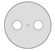
Polarization Axis
|
Name |
Adjustable F (Free) |
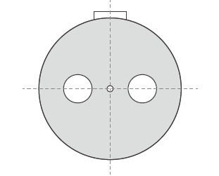
Fast Axis Alignment X (Fast) |
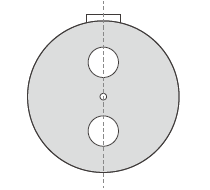
Slow Axis Alignment Y (Slow) |
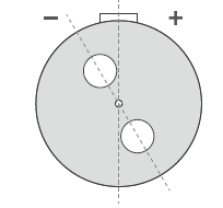
Customer Specified Angle O (Other) |
|---|---|---|---|---|
|
End Face Diagram |
|
|
|
|
|
Description |
The positioning key on the connector is not fixedly assembled, so it can rotate freely when it matches the equipment. It is especially suitable for laboratory or scientific research applications. | The connecting line formed by the centers of the two stress zone and the fibre core is parallel to the center line of the positioning key. |
The connecting line formed. by the centers of the two stress zone and the fibre core is perpendicular to the center line of the positioning key. The polarization direction of most polarized light source devices is also along this direction. |
The angle between the connecting line formed by the center of the stress zone and the center of the fibre core and the center line of the positioning key is specified by the customer |
Specifications
|
Connector Type |
FC/PC, FC/APC, LC/PC, LC/APC, SC/PC, SC/APC |
|||
|---|---|---|---|---|
|
Fibre parameters |
Operating wavelength (nm) |
980 |
1310 |
1550 |
|
Cladding diameter(μm) |
125.0±1.0 |
80.0±1.0, 125.0±1.0 |
||
|
Mode field diameter(μm) |
6.5±1.0 |
6.0±1.0, 9.0±1.0 |
6.5±1.0, 10.5±1.0 |
|
|
Extinction ratio(dB) |
-20 to -30 (1m) |
|||
|
Insertion loss(dB) |
≤0.3 - 1.5 (Determined by cladding diameter and MFD) |
|||
|
Axis deviation(°) |
≤3 |
|||
|
Application environment(°C) |
-10 to +85 |
|||
|
Protective layer(mm) |
Φ0.9, Φ2.0, Φ3.0 Loose Tube, Φ0.9 Tight Tube, Armored |
|||
Related products