Single-Mode/Multimode
Universal Optical Fibre
Compatibility with low-cost light sources VCSEL makes multimode optical fibre the most cost-effective solution for short range transmission. However, limited by the high material dispersion at short wavelengths (850 nm) and large spectral width of VCSEL, further boosting the bandwidth of this fibre cannot improve its transmission capacity and distance. However, the transmission capacity of individual optical fibres can be increased four-fold via transitioning to longer wavelengths and adopting wavelength division multiplexing. Besides optical fibre transmission distance can be greatly extended by introducing quasi-single-mode transmission. Thus YOFC has developed a novel single-mode/multimode universal optical fibre, which combines the advantages of single-mode and multimode optical fibre.
To achieve quasi-single-mode transmission comparable to single-mode optical fibre, most energy of light source should be injected into the fundamental mode of a multimode optical fibre, and then it can transmit over a long distance. Benefiting from YOFC's PCVD technology, single-mode/multimode universal optical fibre has a precisely controlled parabolic refractive index profile and can achieve excellent bandwidth performance over the 850 nm - 950 nm range compliant with the OM5 standard's bandwidth requirements. It has excellent bending insensitivity thanks to a bend-resistant structural design.
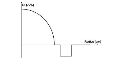
Other than this, reduced core diameter is the most typical feature of this optical fibre. The mode field diameter of its fundamental mode is optimized by a core-cladding structural design to match the mode field diameter of standard single-mode in single-mode transmission systems to achieve quasi-single-mode transmission and reduce multipath interference, so that permitting higher-speed, longer-reach transmission. As shown in Figure 1.

Figure 1 Refractive Index Profile of Single-Mode/Multimode
Universal Optical Fibre
Single-mode/multimode universal optical fibre has a high bandwidth compliant with OM5 standard requirements in wavelength range of 850 nm - 950 nm, as shown in Figure 2, supports wavelength division multiplexing, and is capable of high-speed transmission at 100 Gbit/s or more. Since its mold field diameter of fundamental mode is about 10.3 μm at 1,310 nm, close to that of single-mode optical fibre, this optical fibre can support single-mode transmission at speeds of 100 Gbit/s or above in the 1,270 nm - 1,330 nm wavelength range.

Figure 2 Single-Mode/Multimode Universal
Optical Fibre Bandwidth
Transmission performance of single-mode/multimode universal optical fibre is tested using commercial multimode and single-mode optical transceivers. The programmable pulse generator (PPG) produces a 215-1 pseudo-random binary sequence (PRBS) at a generation rate of 25.78 Gbit/s, while the optical transceivers are controlled by the evaluation board (EB). The received optical power of the transceiver is adjusted using variable optical attenuation (VOA), while the output electrical signal is measured by the bit error rate tester (BERT).As shown in Figure 3

Figure 3 Transmission Test Setup Diagram
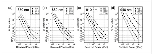
Figure 4, below, shows bit error rate curve results derived from testing the multimode transmission performance of the optical fibre using a Finisar 100G SWDM4 multimode optical transceiver. For all four wavelengths adopted for shortwave wavelength division multiplexing, the bit error rate for 300 m link transmission is lower than the recommended FEC limit (5×10⁻⁵) stipulated in the IEEE 802.3 standard, confirming the transmission distance of single-mode/multimode universal optical fibre at the 850 nm - 900 nm can reach up to 300 m.

Figure 4 Bit Error Rate Curves for Multimode Transmission at (a) 850 nm,
(b) 880 nm, (c) 910 nm and (d) 940 nm
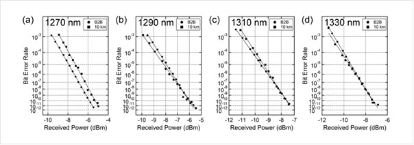
Figure 5, below, reports bit error rate curve results derived from using a commercial 100G CWDM4 single-mode optical transceiver to test the single-mode transmission performance of the optical fibre, demonstrating that the single-mode/multimode universal optical fibre is capable of 10 km bit-error-free (10-12) single-mode transmission in the 1,270 nm - 1,330 nm operating wavelength range.

Figure 5 Bit Error Rate Curves for Single-Mode Transmission at (a) 1,270 nm,
(b) 1,290 nm, (c) 1,310 nm and (d) 1,330 nm
Single-wavelength transmission performances of 100G SR4 and 100G PSM4 have also been tested. The single-mode/multimode universal optical fibre combines the advantages of single-mode and multimode optical fibres. Its bit-error-free transmission distances are given in Table 1, below.
| Transmission Test | Optical Transceiver | Connector | Transmission Distance |
|---|---|---|---|
Multimode |
100G SR4 | MTP/MPO-12 | 350 m |
| 100G SWDM4 | Duplex LC | 300 m | |
Single-mode |
100G PSM4 | MTP/MPO-12 | 10 km |
| 100G CWDM4 | Duplex LC | 10 km |
Table 1 Bit-Error-Free Transmission Distances of Single-Mode/Multimode
Universal Optical Fibre
Multimode transmission is cost effective but limited to short transmission ranges, while single-mode transmission can reach a long transmission distance but at a high cost. Thus each system has its advantages and disadvantages. At present, while adoption of multimode optical fibres and inexpensive VCSEL light sources for construction of short-distance networks is a reasonable strategy. But if a network requires upgrading to higher-speed 1,310 nm wavelength, the system should be converted from multimode to single-mode transmission by relaying of single-mode optical fibres and cables or laying single-mode and multimode hybrid cables at beginning, both of which greatly increase management and maintenance costs.
Single-mode/multimode universal optical fibre is compatible with both multimode and single-mode optical fibres and has excellent transmission performance for both single-mode and multimode transmission systems. Thus it can cover a variety of data center application and upgrade scenarios, and significantly reducing both ongoing network operation costs and the costs of future bandwidth upgrades.
