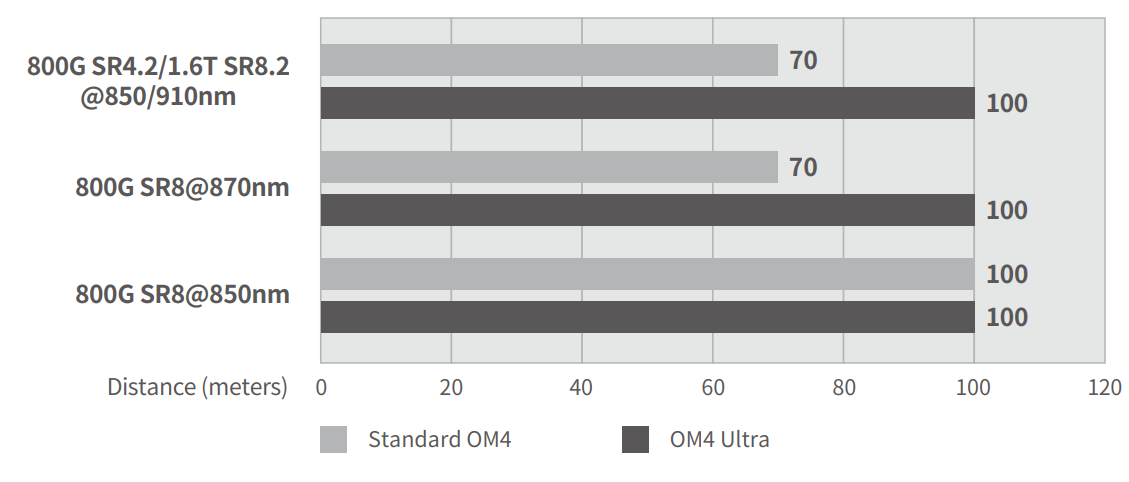
YOFC MaxBand® OM4 Ultra Bending Insensitive Multimode Fibre can support transmission distances of
100m in 100G/lane and Terabit BiDi links which complies with or exceeds IEEE 802.3db specification
and Terabit BiDi MSA specification.

YOFC MaxBand® OM4 Ultra Bending Insensitive Multimode Fibre is designed for 100G/lane and Terabit BiDi technology, offering high bandwidth in the wavelength range of 850nm - 870nm & 910nm. It can compensate the signal degradation caused by the center wavelength shift of 100G/lane transceivers, ensuring smooth upgrades to 400G, 800G, and higher data rates for data centers. It is fully backward compatible with legacy OM4 and OM5 fibres.
YOFC MaxBand® OM4 Ultra Bending Insensitive Multimode Fibre complies with or exceeds ISO/IEC 11801-1 OM4 specification, IEC 60793-2-10 A1-OM4 specification, and TIA-492AAAF A1-OM4 specification.
| Features | Benefits and Applications |
|---|---|
|
|
|
|
|
|
|
|
YOFC MaxBand® OM4 Ultra Bending Insensitive Multimode Fibre can support transmission distances of
100m in 100G/lane and Terabit BiDi links which complies with or exceeds IEEE 802.3db specification
and Terabit BiDi MSA specification.

| Characteristics | Conditions | Specified Values | Units | |
|---|---|---|---|---|
| Geometry Characteristics | ||||
| Core Diameter |
-- |
50±2.5 |
[μm] |
|
| Core Non-Circularity |
-- |
≤5.0 |
[%] |
|
| Cladding Diameter |
-- |
125.0±1.0 |
[μm] |
|
| Cladding Non-Circularity |
-- |
≤0.6 |
[%] |
|
| Coating Diameter |
-- |
245±7 |
[μm] |
|
| Coating/Cladding Concentricity Error |
-- |
≤10.0 |
[μm] |
|
| Coating Non-Circularity |
-- |
≤6.0 |
[%] |
|
| Core/Cladding Concentricity Error |
-- |
≤1.0 |
[μm] |
|
| Delivery Length |
-- |
up to 17.6 |
[km/reel] |
|
| Optical Characteristics | ||||
| Attenuation | 850nm |
≤2.4 |
[dB/km] |
|
|
910nm |
≤2.0 |
[dB/km] |
||
|
1300nm |
≤0.6 |
[dB/km] |
||
| Overfilled Modal Bandwidth |
850nm |
≥3500 |
[MHz·km] |
|
|
1300nm |
≥500 |
[MHz·km] |
||
| Effective Modal Bandwidth |
850nm-870nm |
≥4700 |
[MHz·km] |
|
|
910nm |
≥3100 |
[MHz·km] |
||
| Link Length |
800GBase-SR8 |
100 |
[m] |
|
| 800GBaseSR-4.2 | 100 | [m] | ||
| Numerical Aperture |
-- |
0.200±0.015 |
-- |
|
| Group Refractive Index |
850nm |
1.482 |
-- |
|
|
1300nm |
1.477 |
-- |
||
| Zero Dispersion Wavelength, λ0 |
-- |
1295-1340 |
[nm] |
|
| Zero Dispersion Slope,S0 |
1295nm≤λ0≤1310nm |
≤0.105 |
[ps/(nm2·km)] |
|
|
1310nm≤λ0≤1340nm |
≤0.000375(1590-λ0) |
[ps/(nm2·km)] |
||
| Macrobending Loss1 |
-- |
-- |
-- |
|
| 2 Turns @ 15 mm Radius |
850nm |
≤0.1 |
[dB] |
|
|
1300nm |
≤0.3 |
[dB] |
||
| 2 Turns @ 7.5 mm Radius |
850nm |
≤0.2 |
[dB] |
|
|
1300nm |
≤0.5 |
[dB] |
||
|
Backscatter Characteristics 1300nm |
||||
| Step(Mean of Bidirectional Measurement) |
-- |
≤0.10 |
[dB] |
|
| Irregularities Over Fibre Length and Point Discontinuity |
-- |
≤0.10 |
[dB] |
|
| Attenuation Uniformity |
-- |
≤0.08 |
[dB/km] |
|
|
Environmental Characteristics 850nm & 1300nm |
||||
| Temperature Cycling |
-60℃ to 85℃ |
≤0.10 |
[dB/km] |
|
| Temperature-Humidity Cycling |
-10℃ to 85℃ , 4% to 98% RH |
≤0.10 |
[dB/km] |
|
| Water Immersion |
23℃, 30 days |
≤0.10 |
[dB/km] |
|
| Dry Heat |
85℃,30 days |
≤0.10 |
[dB/km] |
|
|
Damp Heat |
85℃, 85% RH, 30 days |
≤0.10 |
[dB/km] |
|
| Mechanical Specification | ||||
| Proof Test |
-- |
≥9.0 |
[N] |
|
|
-- |
≥1.0 |
[%] |
||
|
-- |
≥100 |
[kpsi] |
||
| Coating Strip Force | typical average force |
1.5 |
[N] |
|
| peak force |
≥1.3,≤8.9 |
[N] |
||
|
Dynamic Stress Corrosion Susceptibility Paraeter(nd, typical) |
-- |
20 |
-- |
|
Remarks: 1. The launch condition for the macrobending loss measurement fulfils that described in IEC 61280-4-1.